
Stirling Engine Diagrams
Which Kind Of Diagram Are You Looking For?
PV Diagrams are near the top. Diagrams of different types of Stirling engines can be found near the bottom.

PV diagram for the Idealized Stirling Cycle.
Explanation of the Diagram Above
The thermodynamics of the idealized Stirling engine cycle (above) are easy to explain.
The gas goes around the diagram and experiences these changes.
1.1. Isochoric heating:
Isochoric heating means heating without moving the piston. Yes, I know that in engines with crankshaft drives, the piston is almost always moving a little bit, but ignore that for now.
The heat source, which can be any form of heat, provides the energy.
You can see that the pressure and temperature will increase as this happens.
1.2. Isothermal expansion:
Isothermal expansion is when the gas pushes on the piston with no change in temperature.
Got it?
The piston has to move in order to get power out of the gas. The engine produces its power during this phase.
As the volume goes increases, the pressure goes down.
1.3. Isochoric cooling:
Isochoric cooling means the piston doesn’t move at all.
During this time, the heat sink (it could be cold water or air) absorbs waste heat.
Hopefully this heat will be used later to do something useful like heat hot water or heat a building, but the engine doesn’t care as long as it is cooled.
Both the temperature and the pressure go down during this part of the cycle.
1.4. Isothermal compression:
Isothermal compression means there is constant temperature.
As gas volume goes down, pressure goes up.
The engine is applying work to the gas during this phase.
Usually, Stirling engines are built with a sinusoidal motion to a displacer driven by a crankshaft.
Since most Stirling engines don’t have any significant dwell time at the ends of the displacer travel, their diagrams have rounded corners like the one above.
Engine with Squarish PV Diagrams

An animation of Ivo Kolin’s First LTD Stirling Engine built in 1984.
Ivo Kolin’s first low-temperature difference engines in the 1980s did this and would have had a similar PV diagram.
But, before you start dreaming up some wonderful new mechanism for doing this, remember that it is easy to have higher mechanical losses, more than make up for the thermodynamic gains you hope to achieve.
So it is possible to more or less build a real engine that approximates, this, but make sure that you weigh the design tradeoffs compared to simpler mechanical designs.
PV Diagram of a Real Stirling Engine

Stirling PV diagram typical of a real engine. Note the rounded corners. Image courtesy Comsol.
The moving parts of all high-speed machines need to have a smooth motion, or the machine will tear itself apart.
High-speed engines of any type will have a PV diagram that looks round on the edges like this one
Now the Other Kind of Stirling Engine Diagram
Diagrams of types of engines: is this what you were looking for?
Please let us know in the comments below.
We also have an excellent page on the most common types of Stirling engine animations, that you also might enjoy.
Here are some more diagrams:
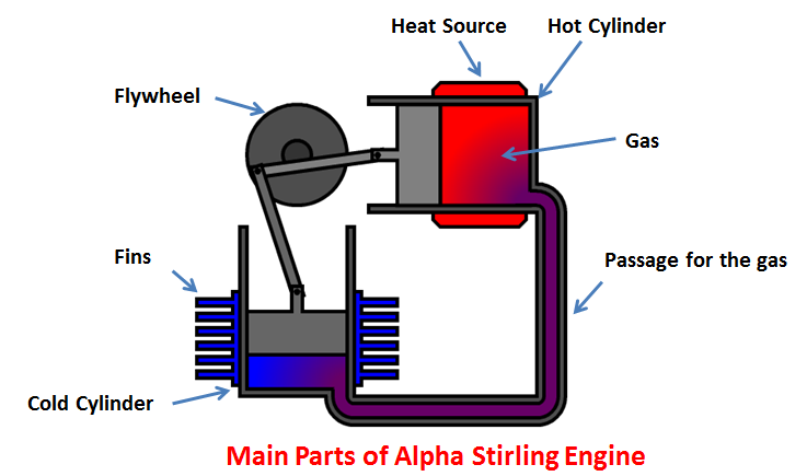
Alpha Stirling Engine Diagram
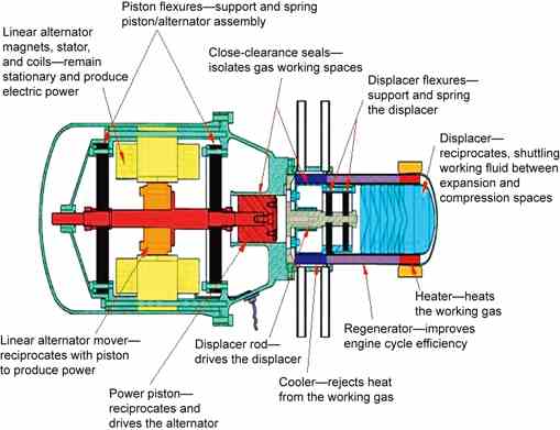
Free Piston Diagram
Two Piston Gamma Type Diagram

Low-Temperature Difference Diagram

Please Check Out Our Model Engines
If you like this page please take a look at our Stirling engine store.
Real PV diagram image courtesy: Phillip Oberdorfer, The COMSOL Group blog.
Alpha Stirling Engine Diagram courtesy: Mechanical Booster
Free Piston Diagram courtesy: Tallbloke Talkshop Blog